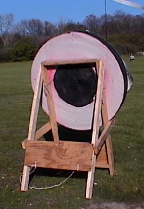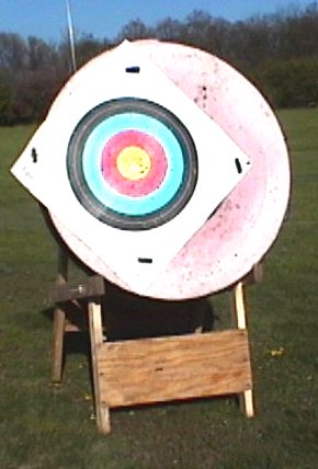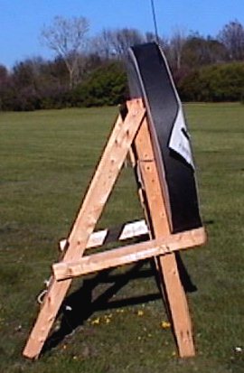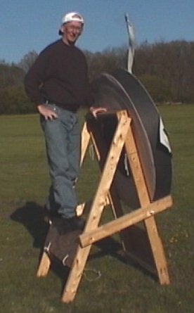


"No, this is not my usual coaching position"
The
following bow stand design and pictures offered here are without restriction.
The purpose is to share with the archery community the results of our research.
The following pictures were taken on Saturday, April 29, 2000 with a Sony
Digital Movie Camera. The stand was rotated around to achieve the
best lighting. Photo credits go to Kathy Miller.
This stand design is
one of the strongest and stable that I have seen. I have been making
this stand with little variance for the past 8 years. We sold matts
and stands at the 1998 NAA JOAD Nationals and many people also took the
stands. Over 40 we sold that weekend with some clubs taking as many
as 8-10.
The stand folds up
for storage and is secured to itself by the 5 1/2" carriage bolts.
The rigidness of the stand is achieved by the two 1/2" plywood sheets.
Below are the materials needed for construction.
4 - 8' 2"X4" pieces of lumber (standard
construction grade pine)
1 - 12"X30"X1/2" plywood
1 - 12"X33"X1/2" plywood
4 - 3 1/2" X 1/4" carriage bolts
2 - 5 1/2" X 1/4" carriage bolts
6 - 1/4" nuts or wingnuts
12- 4" deck screws
12- 2" deck screws
The lumber is cut as follows: (Note:
American 2" X 4" lumber generally measures 1 3/4" X 3 1/2"...this is important)
Two of
the 8' lumber pieces are cut into two, one 60" and 36". The 60" pieces
are used for the front legs and the 36" piece is used for the support arms
for the matt.
The other
two 8' pieces are cut to produce two 61" pieces. The surplus is cut
to 27" for crosspieces for the top and bottom of the front legs.
There will be two 8" pieces to discard.
In order for the pieces to come together and form the pictured stand it is necessary to drill the holes for the bolts at strategic locations on the front and rear legs.
Bottom Top
| > 22.5" o 1.5" from end o |
| > 27.00" o o < 3.0" |
Crosspieces
Front
------------- 36" -------------
| varies >o o < 9.5" |
The rear hole in the crosspieces varies and
can be adjusted to achieve the desired angle of the stand. The crosspiece
should be bolted so that it forms a 90 degree angle to the front leg.
For different diameter target buttresses drill additional holes 1.5" above
and below the 27.00" hole on the 60" leg. Then drill additional holes
in the rear leg and the rear crosspiece hole area. This allows a
variance so that the center of the buttress is the FITA regulation height
above the ground. The 27" hole position is for a 50" Whitetail Industries
Foam Matt.
You will notice the matt is tied on the front
legs. By using standard clothesline rope and two separate pieces
you can secure the matt to the stand. The tie down rope is attached
to the rear plywood piece as shown.
The rigidity of the stand comes from the plywood
pieces. If you are wary of having a large piece of plywood below
the target you can replace it with triangular pieces on the lower front
legs and bottom crosspiece.
When you are ready to store the stand, remove
the front leg 5.5" carriage bolts, fold the front legs inside the rear
assembly. The crosspieces pivot up vertically and another hole can
be drilled through front cross piece hole and through the rear and front
legs and the 5.5" bolt inserted. This prevents the stand from opening
up and facilitates handling problems. This is an option.


"No, this is not my usual coaching position"